Adding Single Monitor Points
in:Flux allows users to define monitor points in five ways:
-
Single - requires an input of the x, y, and z coordinate for a single point or the pick tool can be used to select the location in the CAD model
-
Multi - via the multi pick tool you can continually "pick" locations within the CAD model (pressing Esc will exit). These points will only be editable after clicking the Add Item button
-
Line Spaced - requires an input of two locations to be chosen, a number of points will then be added between the two locations.
-
Area Spaced - a two-dimensional array of monitor points evenly spaced between two coordinates at a specified height
-
Volume Spaced - a three-dimensional array of monitor points evenly spaced between two opposing points of a user defined cuboid
Follow the steps below or watch the following video for defining each:
In this tutorial we will use the single and area spaced methods to add 27 monitor points to the project.
Load your saved Tutorial 2 file into in:Flux before continuing if you haven't already, or you can use the example file located in the inFlux Files for Tutorials 1 - 9.zip (81MB)
Two monitor points will be added first:
-
Click the Add Item tab and select Monitor Point from the dropdown menu.
-
Leave the Name as "Monitor Point 01"
-
Select Single as the Method
-
Maneuver the CAD model so that you can see the walkway on the north side of the facility near the high pressure release as indicated in Figure 01. Use the pick tool to select a point on the walkway as shown in the image or enter the coordinate "(-5.5, 29, 1.78)".
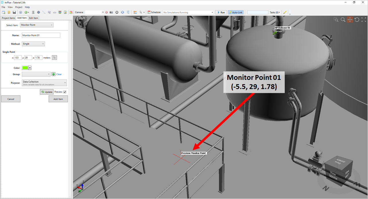
Tutorial 3 - Figure 01 - Indication of Monitor Point 01 coordinate location
-
Leave the Color set as its automatic assignment. You may choose different colors for each monitor point or monitor point series. For the single monitor points, the default color will be used for the individually placed monitor points, we'll use a different color in the next section.
-
Monitors can be added to Monitor Groups to assist in organizing large quantities of monitors and for gas detector optimization. Leave the menu blank for now as this will be discussed in later sections.
-
Leave the Purpose as Data Collection. This tells in:Flux that you want variable data and values (such as %LFL) at this point. The alternative is to have the monitor purpose be assigned as detector optimization, this purpose does not store all the variable data, only coordinate location data, and serves as a plausible location for a gas detector.
-
Click the Add Item button to at the first point to the project. Its name will appear gray in the Project Items tab as it has not been updated with the simulation data yet. The label for the first monitor point can be toggled on by right-clicking the Monitor Point 01 name in the Project Items tab and choosing
 Toggle Label.
 -
Repeat the steps above to add a second point with the name "Monitor Point 02", placing it at a height of someone standing on the walkway. Estimate this to be 2 meters above the Monitor Point 01 location. This can be done by clicking the same point as Monitor Point 01 and changing the z-value to 3.78 or by entering the coordinates "(-5.5, 29, 3.78)" as shown below.
-
Click the Add Item tab to add the second monitor point to the project.
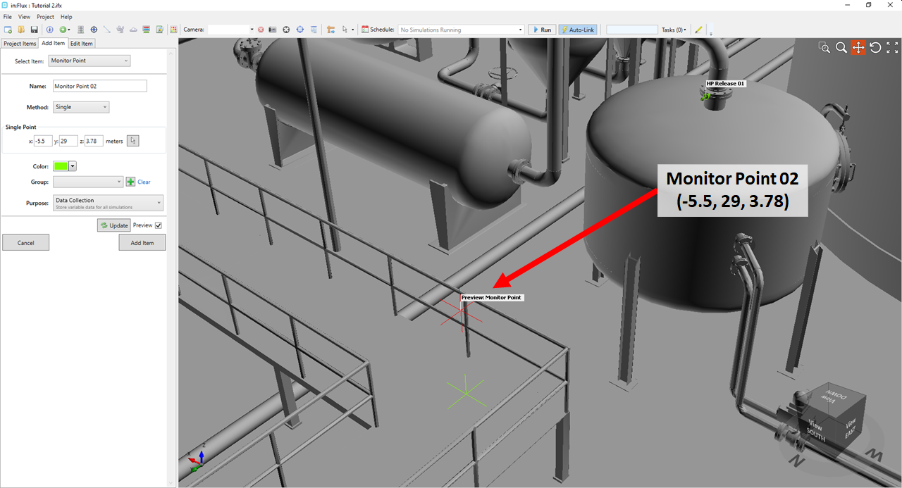
Tutorial 3 - Figure 02 - Location of Monitor Point 02
You can toggle the visibility of all the labels of the monitor points at the same time in the 3D window by right-clicking the Points header and select Toggle All Labels as Figure 03 shows below. This may have to be selected twice as one label is already showing.
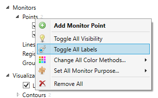
Tutorial 3 - Figure 03 - Indication of selecting Toggle All Labels from the Point header right-click menu.
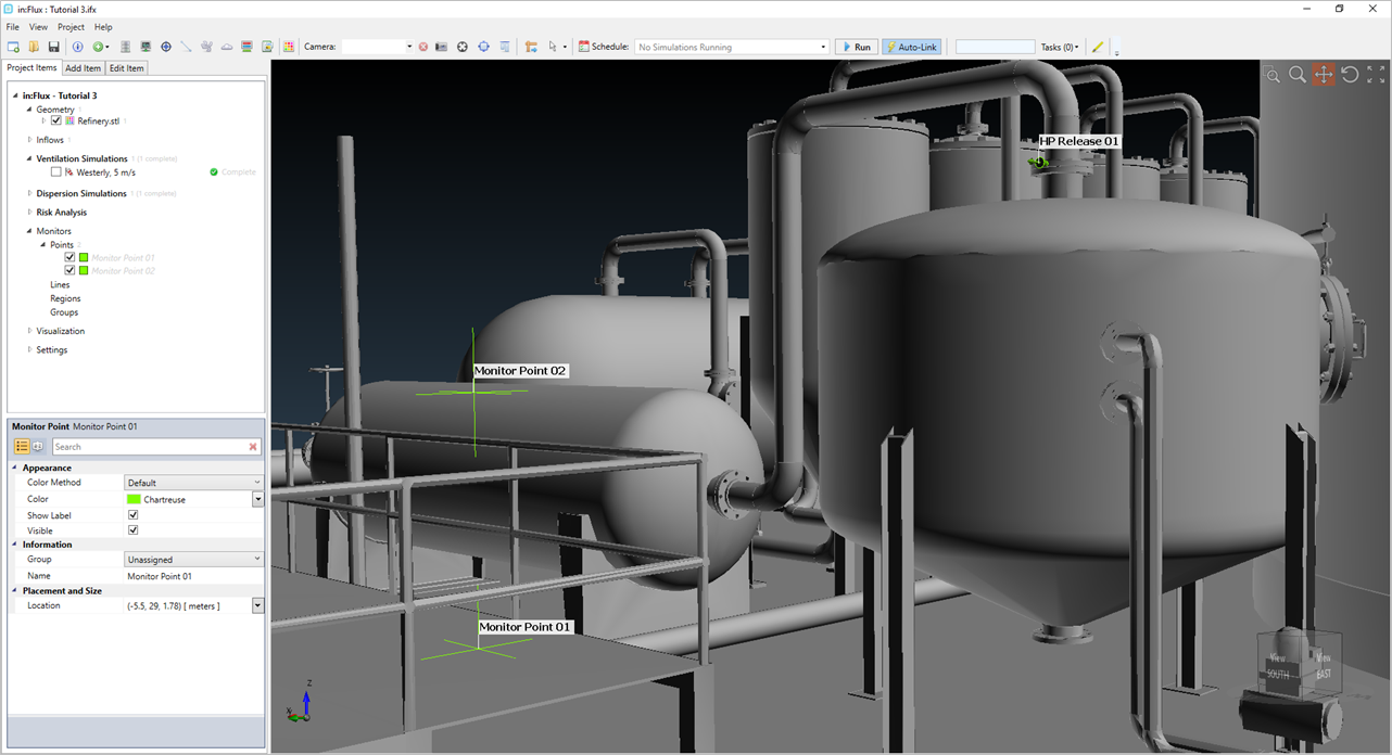
Tutorial 3 - Figure 04 - Location of the two monitor points in the project, with labels.
Continue on to the next section to add a series of monitor points to the project.
Note that the monitor point names will appear in the Project Items tab with a gray text, as in Figure 04, until they are updated with the simulation data from the monitor point data window, which will be discussed in a later section.