Preparing the CAD Model
Start a new project and import the geometry from the Onshore Facility - CAD Only.ifx file.
A typical risk-based project contains hundreds to thousands of CFD cases so any simplification of the geometry that can be done can significantly reduce the total computation time of the project.
For this file, the entire facility has been provided but we will be analyzing the region on the west end of the site, indicated below. For simplicity we will only use the Crop Tool in this tutorial to remove the CAD items not pertinent to the analysis region. Ideally, rather than ignoring CAD items, far-field CAD could be represented using porous regions or creating simple 3D CAD. Sensitivity studies can be performed on the geometry simplification to check that there are no significant differences between using the full model and the simplified/approximate model. Follow this link to download our Risk-Based Gas Mapping Workflow document which goes into some of the preparation steps in more detail.
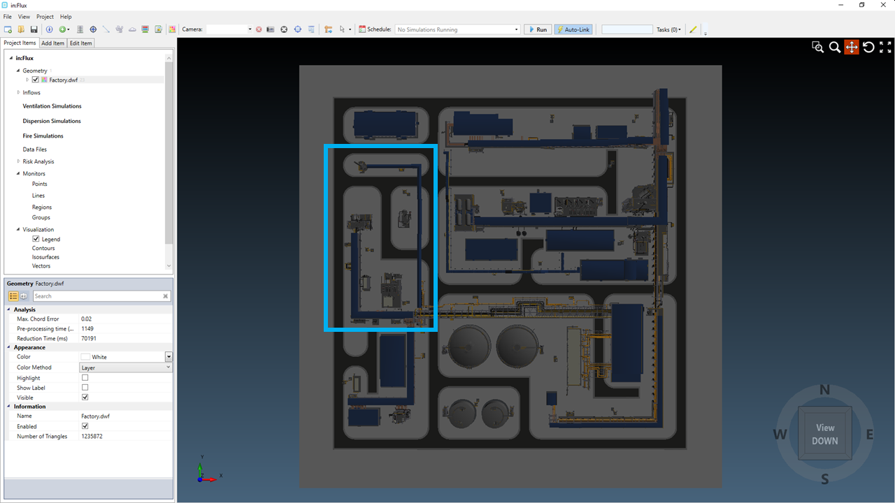
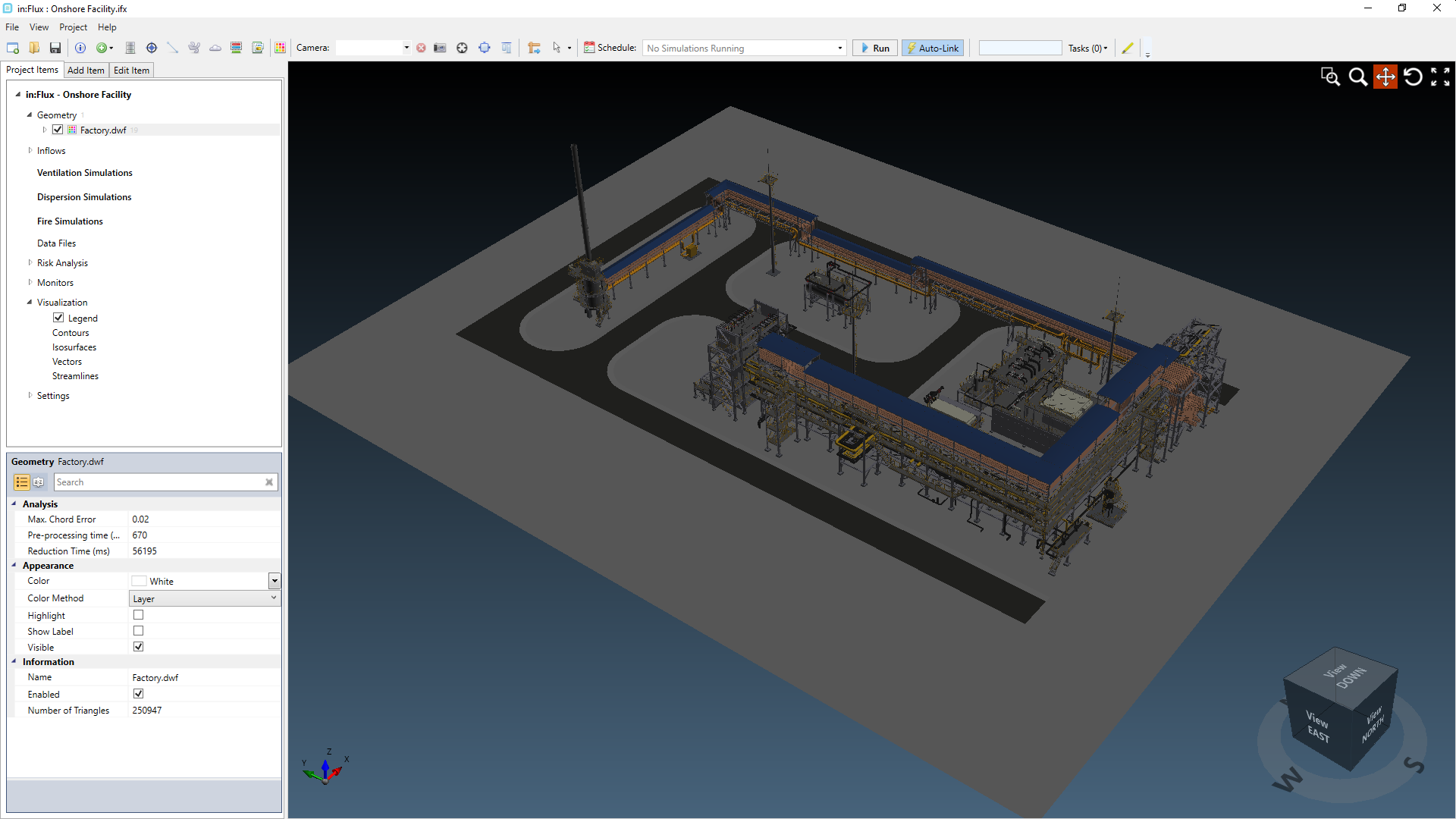
Tutorial 11 - Figure 01 - Imported Onshore Facility model with indication for region needing analysis
To Crop the model:
-
Open the Crop Tool from the Project Menu. In the window that appears you can enter two opposing points of a cuboid to crop around, this is similar to how monitor regions are defined.
-
To match this tutorial, enter the following coordinates for Point 1 ( 88, 151, -2) and enter ( 0, 0, 45 ) for Point 2. The z-values don't have to be exact as we just want the ground and street CAD items to remain so a negative number below the ground height is used. Similar with the second point having a higher z-value than the tallest CAD item.
-
Ensure the yellow bounding box is similar to the figure below, then set the Remove Geometry option to Outside the box and click the Crop button
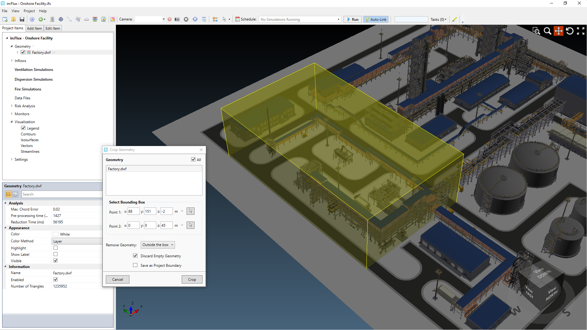
Tutorial 11 - Figure 02 - Cropping Bounding Box for the Facility CAD model
As the ground triangles were larger than the cropping bounding box the ground CAD was removed. You can choose to then add a ground using the CAD Creation Tool, described below, or you may leave the model as is and continue to the next section of the tutorial. When running the CFD cases, the ground height is defined when you first setup a ventilation case or from the project menu. Doing this sets the lower boundary layer of the analysis so a CAD item representing the ground is more for visualization purposes.
Creating a Ground using the CAD Creation Tool
-
Right-Click on Factory.dwf geometry in the Project Items Tab and choose Edit
-
The CAD Creation Tool interface will appear. On the right-panel you will see a list of all the layers. In the upper right corner, click the plus sign icon, shown below, next to the Active Layer dropdown menu. This will add a new layer to the list on the right side panel.
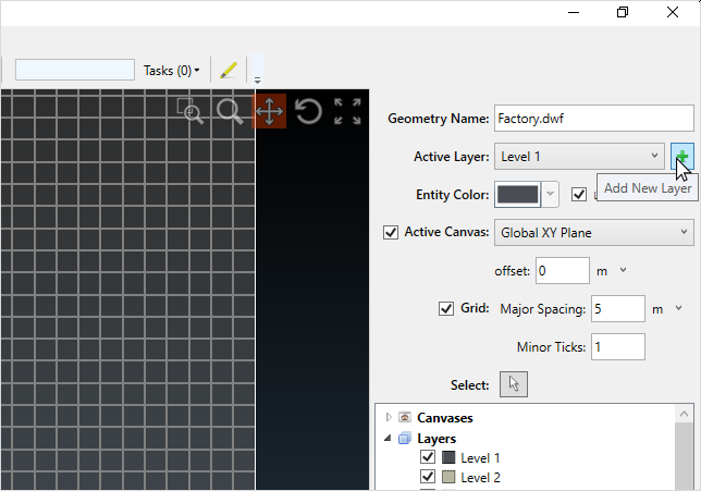
Tutorial 11 - Figure 03 - Adding a new layer via the CAD Creation Tool
-
Click the layer name in the panel and in the bottom right corner of the window change the Name of the layer to "Ground" and choose a color for it.
-
Once defined, select the newly named Ground layer to be the Active Layer from the dropdown menu in the upper right corner of the window. Any new surfaces will now be added to this layer.
-
Now for drawing the ground item. On the left side of the window, ensure the Surface/Type is set to Box/Plane from the 3D Surfaces tab and enter the following coordinates, Point 1 ( -35, 172, 0 ) and Point 2 (121, -25, 0 ). Alternatively, you may use the Quick Box Tool
 to drawn a square encompassing the CAD items and
then manually entering the z-coordinates of both points to be 0.
to drawn a square encompassing the CAD items and
then manually entering the z-coordinates of both points to be 0. -
Confirm the red square encompasses the CAD model as in the figure below and click the Add Box button on the left side of the screen.
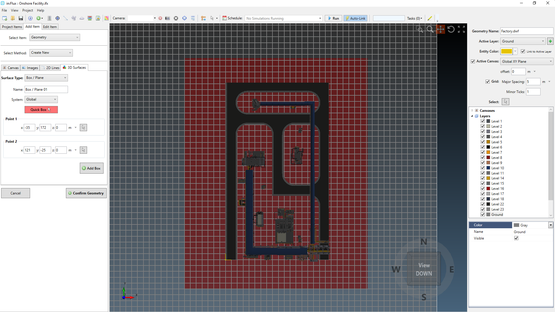
Tutorial 11 - Figure 04 - Preview (in red) of Box/Plane being defined to the newly added Ground layer
-
With the ground item defined (changes from a transparent red square to the color of the layer), click the Confirm Geometry button.
Your window should now appear as the figure below and you may continue on to the next section to start defining leaks with the risk-manager.
Tutorial 11 - Figure 05 - Cropped Facility.dwf file with new Ground CAD item defined.