Defining inflows with the Risk Manager
Similar to Tutorial 11, inflows for fire cases can be defined using the risk manager. Using this tool allows for several inflows to be defined, copied and edited to assist in setting up 10s to 100s of leaks at the same time. High pressure leaks can be added by following the steps below and pool fire inflows can be added first by creating them in the Add Items Panel via the Custom Gas Emissions option. Once defined there, they may be selected in the risk manager.
This section will first create a multi-component mixture and then add 20 inflows using the risk manager.
Creating a Gas Mixture
From the Add Item Tab, choose Gas Definition as the Select Item:
-
Leave the Name as Mixture and add the following components with the provided concentrations, follow this link to Tutorial 7 for further instructions on how to add components to a gas mixture:
-
Methane - 90%
-
Ethane - 6%
-
Propane - 4%, recall for the last component leave the suggested value in the Concentration text box before pressing Add.
-
-
Ensure your window is similar to the figure below and press the Add Item button
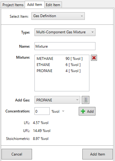
Tutorial 19 - Figure 5 - Gas Mixture Definition for Tutorial 19 example
Defining inflows for the project using the Risk Manager
For this example, sets of 3, 4 or 2 leaks will be defined at varying locations on values located on the upper deck. Follow the steps below first but a file may be downloaded later in the tutorial with the completed results.
-
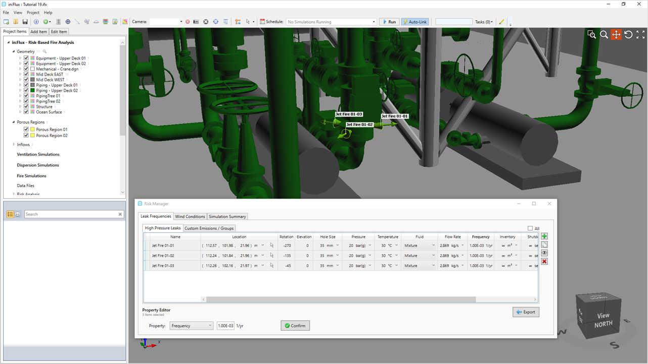
Open the Risk Manager
 from the Project Menu and click the plus icon (
 ) on the right side of the window. A new row will appear in the Risk Manager with columns representing the properties of the leak. Each property can be edited by clicking in the cell, highlighting the current value and
entering a new one or by selecting a row and using the Property Editor at the bottom of the window.
) on the right side of the window. A new row will appear in the Risk Manager with columns representing the properties of the leak. Each property can be edited by clicking in the cell, highlighting the current value and
entering a new one or by selecting a row and using the Property Editor at the bottom of the window. -
Enter the following properties for this leak, leaving the position as its default for now:
-
Change the Name to "Jet Fire 01 - 01"
-
Enter the Hole Size to "35mm"
-
Enter the Pressure as "20 bar(g)"
-
Enter the Temperature as "30°C"
-
Select the newly created Mixture from the top of the dropdown menu for the Fluid and leave the other values as their defaults.
-
-
With these properties set, click the copy icon
 twice, this should automatically increment the name adding Jet Fire 01-02 and Jet Fire
01-03 leaks with the same properties as above.
twice, this should automatically increment the name adding Jet Fire 01-02 and Jet Fire
01-03 leaks with the same properties as above. -
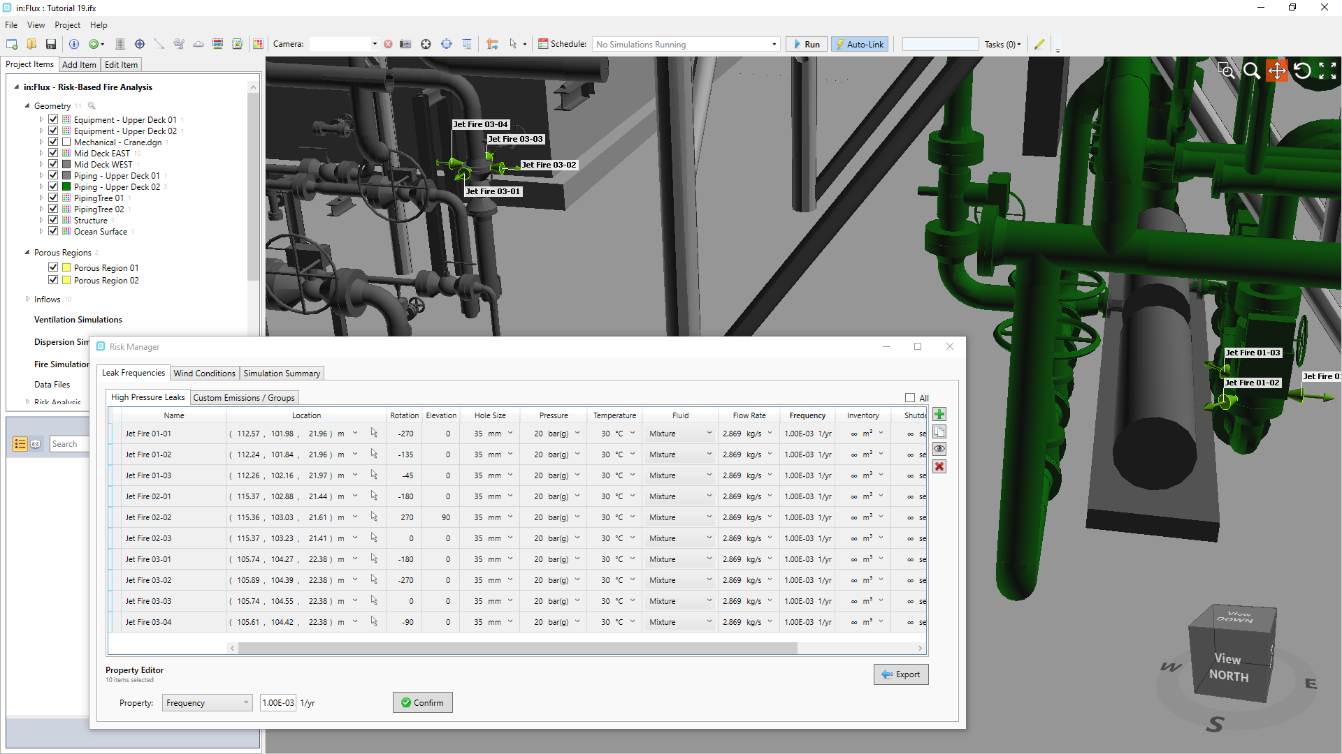
Highlight all three leaks and using the Property Editor, enter the Cumulative Frequency as 3.00E-03 which will assign a value of 1.00E-03 to each (you may also choose to manually enter this value for each).
-
Now we have created a set of three leaks which will be positioned around a flange indicated in the figures below. Alternatively you may manually enter the following information:
-
Jet Fire 01-01: Position ( 112.57, 101.98, 21.96 ), Rotation as -270 , Elevation as 0
-
Jet Fire 01-02: Position ( 112.24, 101.84, 21.96 ), Rotation as -135, Elevation as 0
-
Jet Fire 01-03: Position ( 112.26, 102.16, 21.97 ), Rotation as -45, Elevation as 0
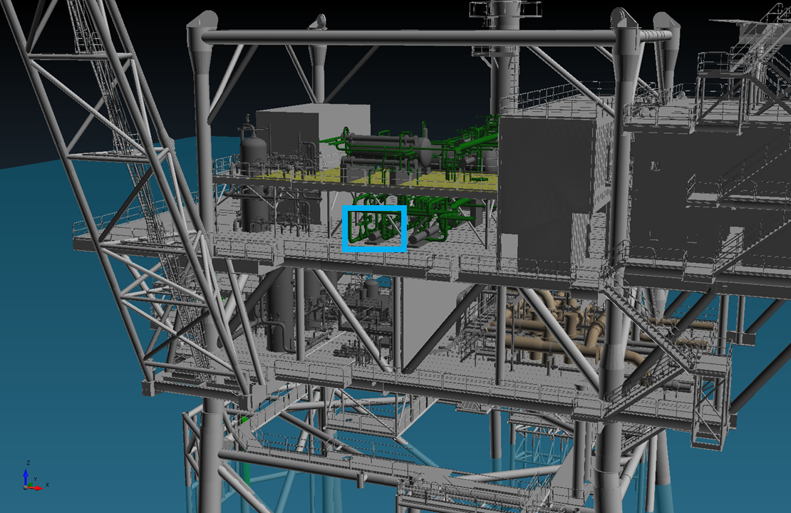
Tutorial 19 - Figure 6 - Indication of where to define the leak location (part 1 of 2)
Tutorial 19 - Figure 7 - Indication of where to define the leak location (part 1 of 2)
-
-
With three leaks defined for the first location, highlight all three rows and press the copy button
. Change the name of the newly
added three leaks to Jet Fire 02-01 Jet fire 02-02, and Jet Fire 02-03. You may also use your own naming convention but for the purposes of this tutorial the first number will represent the location number and the second as the leak number at
that location. -
Move over to the next pump to the east and position the three leaks as in Figure 8 below using the pick tool or enter the following coordinates
-
Jet Fire 02-01: Position ( 115.37, 102.88, 21.44 ), Rotation as -180 , Elevation as 0
-
Jet Fire 02-02: Position ( 115.36, 103.03, 21.61 ), Rotation as 270, Elevation as 90
-
Jet Fire 02-03: Position ( 115.37, 103.23, 21.41 ), Rotation as 0, Elevation as 0
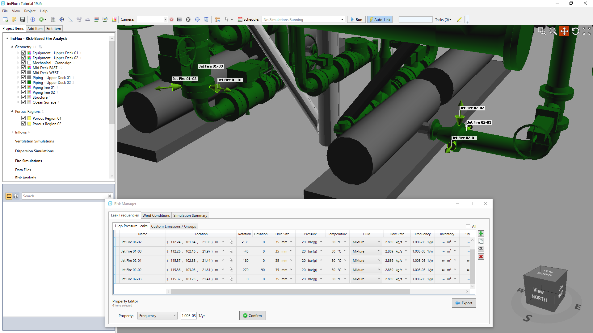
Tutorial 19 - Figure 8 - Indication of where to define the second leak locations
-
-
Now add an addition four leaks with the same properties as before named Jet Fire 03-01, Jet Fire 03-02, Jet Fire 03-03 and Jet Fire 03-04. You may do this by clicking the add button and editing each cell individually or using the copy button and re-naming three leaks and then copying a single case for the fourth. Move to the grey pipework to the west of the leaks defined in Step 5 and Step 7 above and define a leak in each of the cardinal directions as shown in the figure below
-
Jet Fire 03-01: Position ( 105.74, 104.27, 22.38 ), Rotation as -180 , Elevation as 0
-
Jet Fire 03-02: Position ( 105.89, 104.39, 22.38 ), Rotation as -270, Elevation as 0
-
Jet Fire 03-03: Position ( 105.74, 104.55, 22.38 ), Rotation as 0, Elevation as 0
-
Jet Fire 03-04: Position ( 105.61, 104.42, 22.38 ), Rotation as -90, Elevation as 0
Tutorial 19 - Figure 9 - Indication of where to define the third set of leaks
-
-
As there are four sets of leaks for location 03, the frequency should be updated. Highlight all four rows representing Jet Fire 03 leaks and set the Cumulative Frequency of 3.00E-03 which will assign a value of 7.5E-04 to each.
-
If there is duplicate or similar pipework, then leaks can be translated and copied at the same time. For the fourth set highlight the four rows representing Jet Fire 03 leaks and change the Property Editor to Position. Activate the vector pick tool (
 ) and select a southern facing point on the flange location of Jet Fire 03 leaks (seen in Figure 10 below). Then zoom into the similar
flange on the deck above, selecting the similar point as the first flange. This will record the delta vector between the two points. Click the Copy and Confirm button to make a copy of the four leaks and position them around the flange
selected on the upper deck (shown in Figure 12).
) and select a southern facing point on the flange location of Jet Fire 03 leaks (seen in Figure 10 below). Then zoom into the similar
flange on the deck above, selecting the similar point as the first flange. This will record the delta vector between the two points. Click the Copy and Confirm button to make a copy of the four leaks and position them around the flange
selected on the upper deck (shown in Figure 12).-
Alternatively, you may enter the delta vectors of ( 0.51, 0.05, 4.01 ) and press Copy and Confirm to match the below images
-
Once the copies are made, change the Names to Jet Fire 04-01, Jet Fire 04-02, Jet Fire 04-03 and Jet Fire 04-04
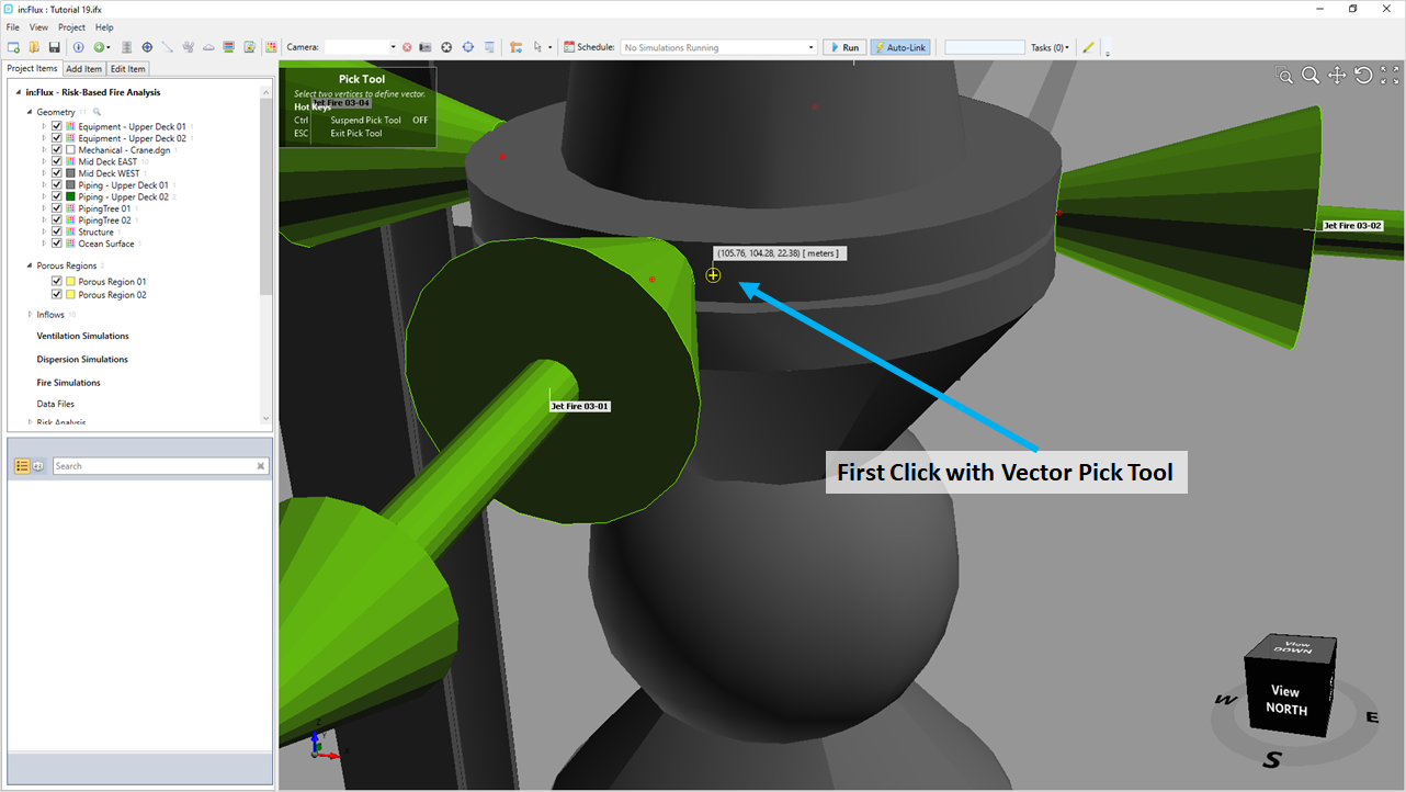
Tutorial 19 - Figure 10 - Selecting the first point for the vector pick tool
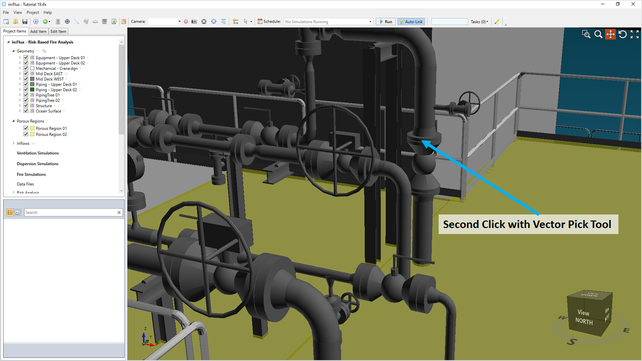
Tutorial 19 - Figure 11 - Selecting the second point for the vector pick tool
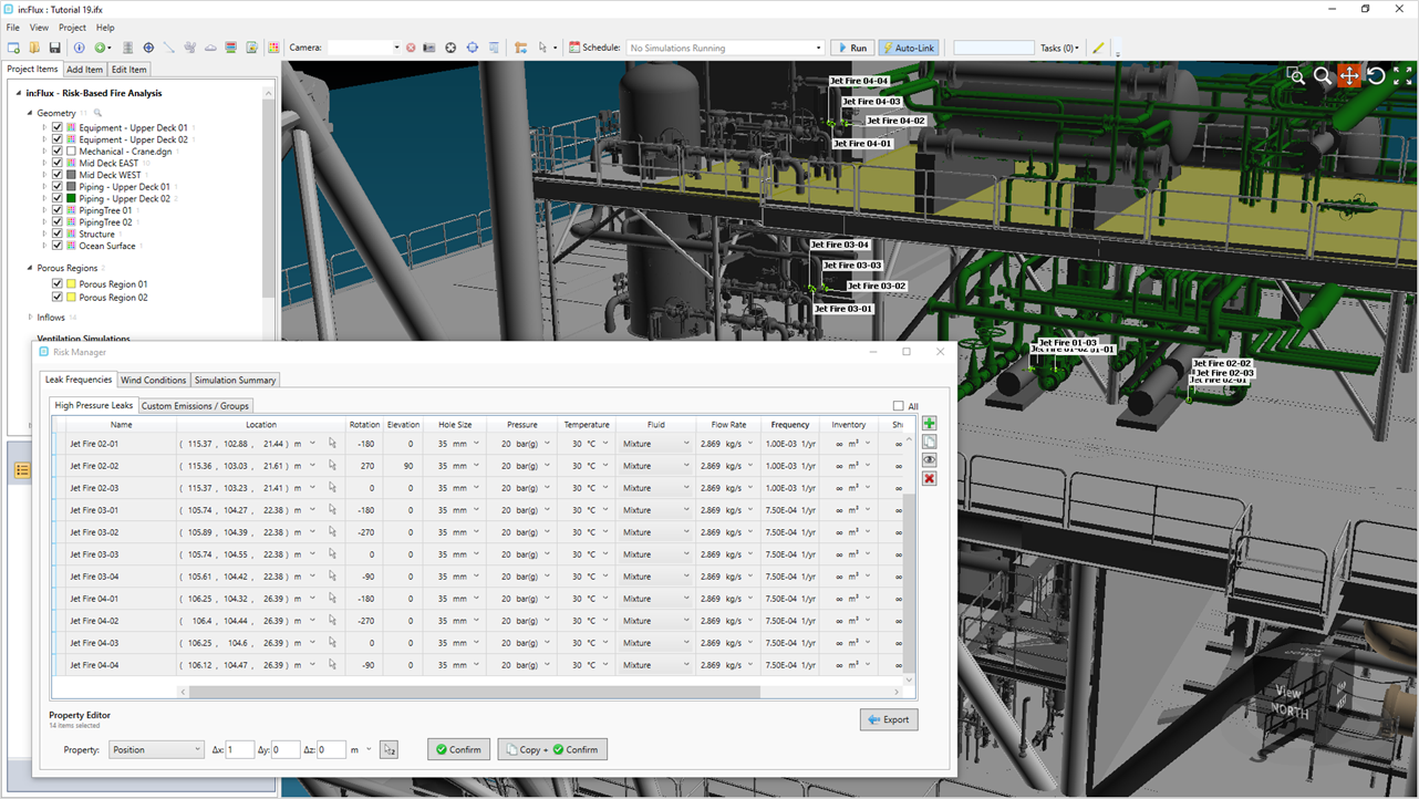
Tutorial 19 - Figure 12 - Showing four sets of leaks defined with the risk manager
-
-
Use one of the mentioned methods above and define eight more leaks covering two more pieces of equipment. Note that these leaks are intended to be grouped together representing one equipment item rather than individual flanges. It is up to your and your project on what is the best method for leak locations, directions and quantities. As combining some leaks for a single equipment item (and properly distributing the frequency values) rather than individual flanges can significantly reduce computation times as not nearly as many cases will be simulated. For convenience the locations, rotation and elevation values are provided below. A file with the leaks already defined will be provided in a later section:
-
Jet Fire 05-01: Position ( 116.99, 104.48, 26.18 ), Rotation as 90 , Elevation as -45
-
Jet Fire 05-02: Position ( 116.86, 104.13, 27.88 ), Rotation as -90, Elevation as 45
-
Jet Fire 05-03: Position ( 116.99, 106.98, 27.89 ), Rotation as 90, Elevation as 45
-
Jet Fire 05-04: Position ( 116.85, 107.32, 26.5 ), Rotation as -90, Elevation as -45
-
Jet Fire 06-01: Position ( 111.74, 109.78, 21.86 ), Rotation as -180 , Elevation as 0
-
Jet Fire 06-02: Position ( 111.57, 109.9, 22.67 ), Rotation as -90, Elevation as 0
-
Jet Fire 06-03: Position ( 114.65, 110.04, 21.86 ), Rotation as 0, Elevation as 0
-
Jet Fire 06-04: Position ( 114.83, 109.91, 22.67 ), Rotation as 90, Elevation as 0
-
-
Check and see that you now have 22 leaks defined in the risk manager as seen in the following figures
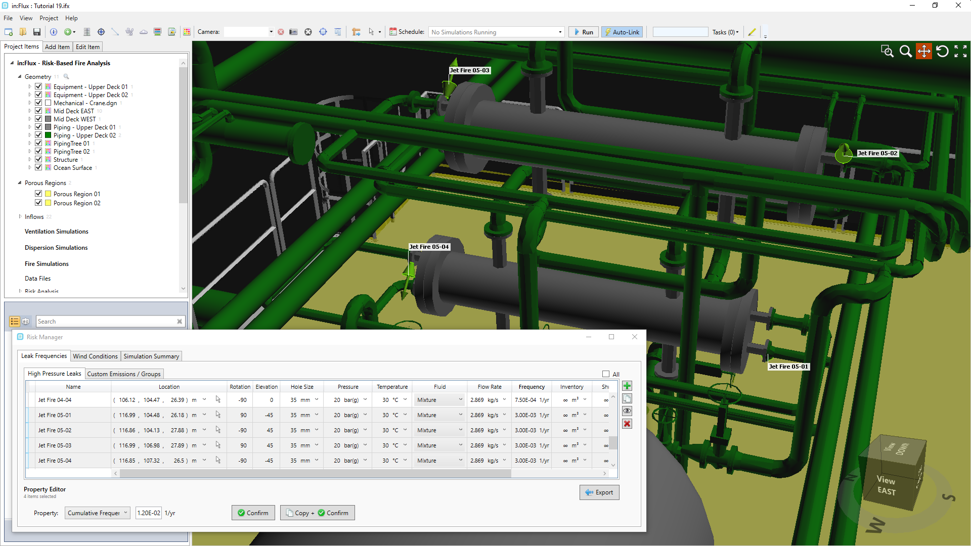
Tutorial 19 - Figure 13 - View of Jet Fire Leak Location 5
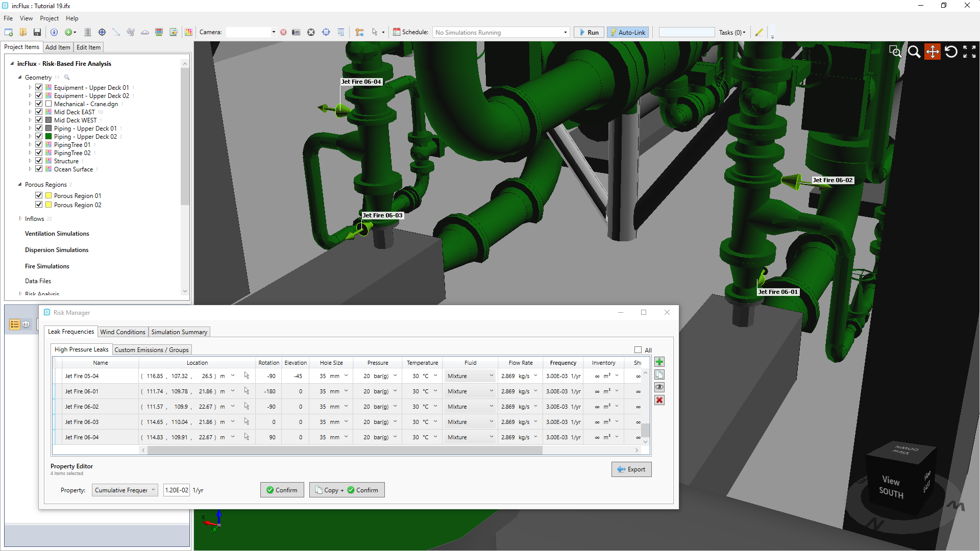
Tutorial 19 - Figure 14 - View of Jet Fire Leak Location 6
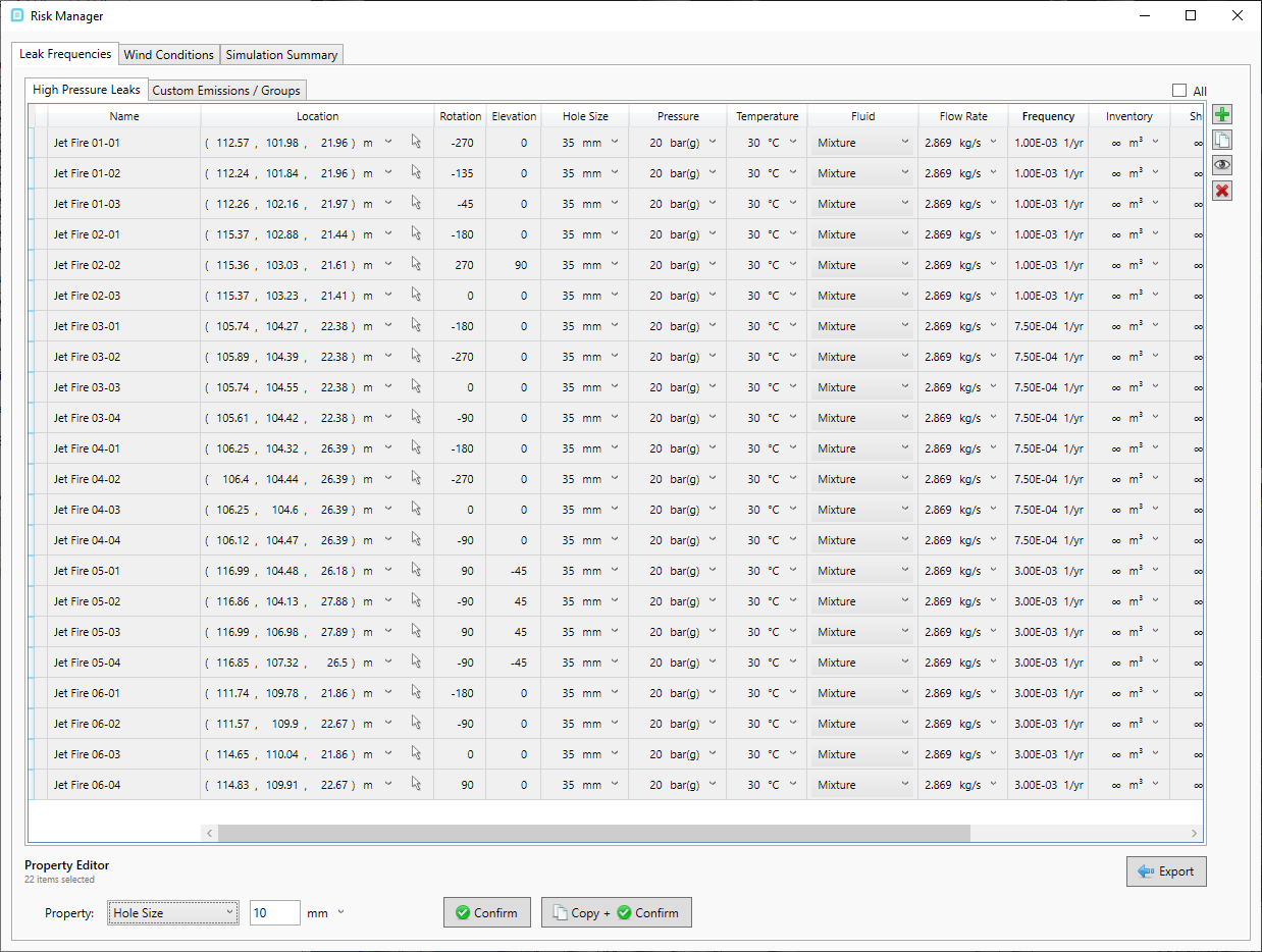
Tutorial 19 - Figure 15 - All leaks defined for Tutorial 19
You should now have an understanding of adding leaks with the Risk Manager and editing their properties. This process can be repeated for several hundred leaks in a facility.
Continue to the next section to define a wind rose for the jet fire simulations.