Risk Grade Properties
Each risk grade in Detect3D has several properties associated with it. This section will briefly go over each. You can view, import, export and reorder the risk grades in your Detect3D project from the Performance Standard option located under the Project Menu or by selecting the icon (![]() ) on the toolbar.
) on the toolbar.
Risk Grade Property Descriptions:
Base Color
There is a color associated with each risk grade. The default colors for risk grades A, B, and C have been chosen for ease of understanding and clarity. You can change the color or name of a risk grade from the properties panel once a risk grade has been selected from the project items tree.
Description
You may choose to add a description of the risk zone. This description will appear on the reports generated in Detect3D.
Hidden
If selected, the Risk Grade will not appear in the coverage results table. The Default Grade is defaulted to hidden.
Is Visible
A non selectable item which displays either True or False, indicating if the current risk grade is the visible risk grade in the 3D window. To make a Risk Grade visible, right-click its name in the project items tab and select 'Make Visible'. Contour and isovolume visualizations will be affected by which risk grade is currently visible. Note: even if a risk grade is currently visible, it will only affect coverage value if the risk grade is assigned to a zone or sub-zone.
Name
The name of the associated risk grade.
≥1ooN Coverage
Value automatically entered into the optimization controller's 1ooN coverage target when Overwrite with Performance Standard is selected. This value is also stored in the Performance Standards Table, ![]() on the toolbar.
on the toolbar.
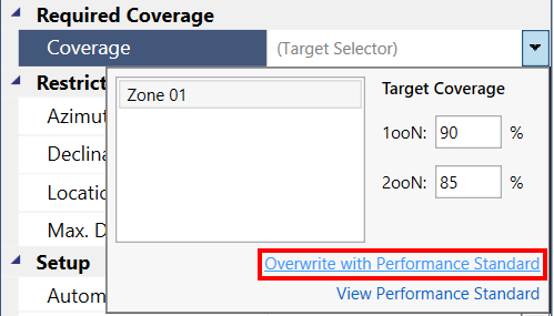
Tutorial 5 - Figure 01 - location of where entered 1ooN and 2ooN coverage values can be used
≥2ooN Coverage
Value automatically entered into the optimization controller's 2ooN coverage target when Overwrite with Performance Standard is selected. This value is also stored in the Performance Standards Table, ![]() on the toolbar.
on the toolbar.
Default Expansion Radius / Sub-Zone Expansion
This sets the value that appears in the radius text box, shown below, for the equipment pick tool when the risk grade is selected for adding a sub-zone to the project. The value represents how far away the sub-zone will be defined from selected equipment pieces.
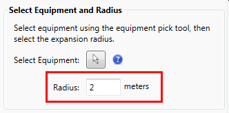
Tutorial 5 - Figure 02 - Location of Expansion Radius when defining sub-zones
FOV Multiplier
The Field-Of-View Multiplier is a value for which is multiplied to the maximum range for any given detector in the project. A value of 1 indicates no change to a detector's field-of-view. This property is useful in conjunction with the Inverse Square Law in determining field-of-view sizes for a fire size (RHO) different than that which the detector manufacturer specifies. You may use the Inverse Square Tool in Detect3D (located under the Project Menu) to calculate corresponding field-of-view ranges. However, when using this feature, it becomes a question of what RHO did manufacturer’s test for, i.e. what is the RHO of a 1ft x 1ft pool fire? Some have taken this to be 10 kW/m2, while others have conclude this to be around 37.5kW/m2, referenced by the SFPE manual (section 2, chapter 3) as well as some papers by the University of Bologna (section 3.2 specifically). It is up to the user to decide what is more applicable to their analysis as each project will be different.
Note: The Inverse Square Law Calculator is not a replacement for manufacturer's data.
Gas Cloud Size (Low Alarm)
The value (defaulted to 5 meters) will change the low alarm gas cloud size for the point and open path gas detectors associated with this risk grade. Tutorial 6 goes into more detail on changing gas cloud sizes. If voting logic is set to LoLo this will be the only gas cloud size for the project.
Gas Cloud Size (High Alarm)
The value (defaulted to 5 meters) will change the high alarm gas cloud size for the point and open path gas detectors associated with this risk grade. Tutorial 6 goes into more detail on changing gas cloud sizes. This is generally smaller than the low alarm size.
Acoustic Detector Voting Logic
Allows user to select how acoustic devices contribute to coverage. Options of 1ooN and 2ooN+ (the default) or 2ooN+ Only exist.
Control Voting Logic
Options of LoLo, LoHi or HiHi which corresponds to how 2ooN coverage is displayed for the Low and High Alarm gas cloud sizes defined. See this section for more details about the voting logic for risk grades.
Gas Type
Gas detectors in Detect3D can be one of two types: Combustible or Toxic. When defining a new Risk Grade or editing an existing one you can change the gas type by choosing the desired option from the associated dropdown menu. The coverage values calculated for a zone will be based on the zone's risk grade, thus if the gas type of a risk grade is set to toxic, ONLY the gas detectors set as toxic will contribute to the zone's coverage. Tutorial 8 goes over toxic gas mapping with Detect3D.
If your gas detector field-of-influence (FOI) is a gray color then check what the "type" the gas detector is and right-click it in the Project Items Tree and select Make Visible to display the updated gas cloud to the corrected type.
Gas Cloud Concentration
The LEL or ppm value used for gas mapping. The units of this value automatically change with the selected Gas Type for the Risk Grade.
Due to the geographic analysis method, this value will change the FOI for the open-path gas detectors but not the point gas detectors. This is because the point detector only responds to the local concentration, and as long as that is above the alarm setting, it will be in an alarm state. This is not true for open-path gas detectors, because the part of the sphere that intersects the path returns a signal that is proportional to the concentration of the gas cloud (i.e. an integration of the concentration profile, which in the case of a sphere intersecting the open-path detector, is just a step function).
The alarm setting for the open path devices is based on the LEL.m variable, requiring a particular concentration of gas to cross the beam to go into alarm, e.g. if 1 LEL.m is needed to set the detector into alarm this is equivalent to 1 meter of 100% LEL gas cloud crossing the beam (Figure 3) or 5 meters of 20% LEL gas cloud (Figure 4).

Tutorial 5 - Figure 03 - Description of open-path gas detector 1 LEL.m alarm setting for 100% LEL concentration

Tutorial 5 - Figure 04 - Description of open-path gas detector 1 LEL.m alarm setting for 20% LEL concentration