Tutorial 9 - Internal Ventilation Simulations
All tutorials prior to this one have used an external ventilation simulation - simulating airflow outside and around buildings or structures. This tutorial will go over how to simulate internal ventilations within buildings.
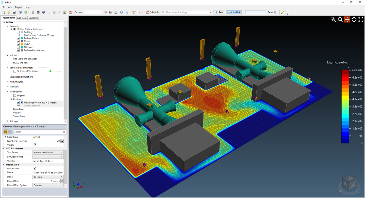
This is commonly done to show compliance for gas detector placements or show a building is adequately ventilated. The tutorial will go over an example case for a gas turbine enclosure - simulating an internal ventilation and then calculating a dispersion within the building. This would resemble an analysis for the UK HSE Guidance Note PM84.
HVAC inflows such as inlets, outlets and flow-through fans can be added throughout the domain of the building. The inlets and outlet flow rates MUST sum up to equivalent amounts.
Although this CAD model is an approximation, porosity can be added around the turbine to represent the complex pipework that would normally exist. For simplicity, only the loaded CAD model will be used with this tutorial.
In this tutorial you will learn how to:
-
Define a HVAC inlet
-
Define a HVAC outlet
-
Setup and run an internal ventilation with HVAC inlets and outlets
-
Setup and run a dispersion case using the interval ventilation
Files used in this tutorial:
-
Gas Turbine Enclosure.ifx (<1MB) - included in the inFlux v2.0 Tutorials 01 - 09.zip (84MB)
The Gas Turbine Enclosure.ifx file is also located in the tutorials folder of the in:Flux directory (usually C:\Program Files\inFlux\Tutorials depending on the folder chosen during installation). Alternatively, you can load it from the Help menu.
Contents of Tutorial 9: