Risk Analysis with Internal Ventilation
Risk-Based Gas Mapping can be used to perform gas detector optimizations with internal or indoor ventilations. Follow the steps below to setup this project type as it is different than the Tutorial 11 example using external ventilations.
Setting up the internal ventilations
-
Define the needed HVAC Inlets and HVAC outlets for your project. The below example will use the Tutorial 9 file, but you can define as many inlets and outlets as needed for your project.
-
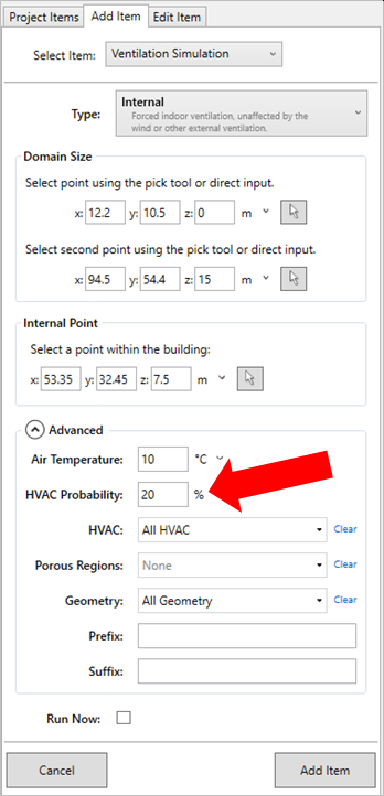
Setup the internal ventilation as normal,
-
Set the bounds for the domain of the internal space
-
Ensure the internal point in inside the space but not inside equipment
-
Open the advanced section and choose the HVACs to include for this case.
-
Here, you can also set a probability for the case.
-
-
Add the case to the project
-
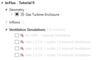
Repeat Steps 2-3 as needed, defining multiple internal ventilation cases using sub-sets of the defined HVAC depending on what's needed for your facility. It is suggested to add a Prefix name to help distinguish between each case.
- This example below shows 4 internal ventilations defined using various HVAC inlets and outlets.
-
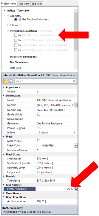
Once defined the probability for each case can be changed in its properties panel.
-
Additionally, once the internal ventilation cases have been defined you can open the risk manager (
 ) and select the Ventilation Probabilities tab to see each case, the included
HVAC and the probability. The normalize button on the right can be used to normalize the probability values in the ventilation tab so they all add up to 100%. This should be done before continuing.
) and select the Ventilation Probabilities tab to see each case, the included
HVAC and the probability. The normalize button on the right can be used to normalize the probability values in the ventilation tab so they all add up to 100%. This should be done before continuing.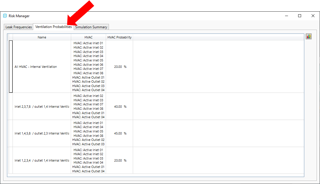
-
From here you may go about adding leaks using the leak frequencies tab as described in Tutorial 11.
-
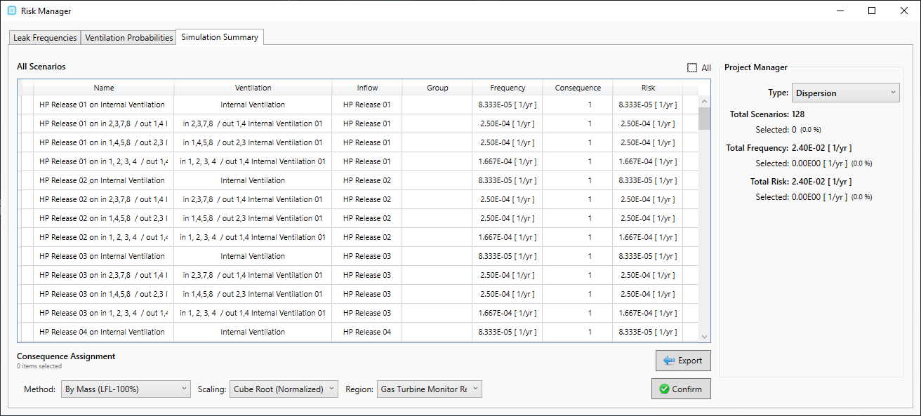
Once all leaks and ventilation cases have been defined, the simulation summary will display the number of dispersion cases and associated frequency values. In the below, 32 leaks were defined which results in 128 dispersion simulations using the 4 ventilation cases.
-
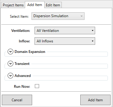
For internal ventilation projects, dispersion cases need to be defined using the Add Items tab, shown below. Selecting All Ventilation and All Inflows cases before adding them to the project.
-
Before leaving the project to run, define any needed Risk Data Sets to collect data as simulations complete.
Running Internal Ventilation Dispersion Cases
Depending on the size of your project you may have all the cases run in series on a single machine. Alternatively, the ifx:Solve software may be used with created solver files to expedite the computation of large projects. Please email info@insightnumerics.com with any questions about setting up or running your project with the ifx:Solve software.
Reviewing Results for Risk Analysis with Internal Ventilations
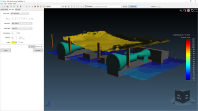
Once complete, exceedance contours and isosurfaces can be defined as with other risk-based projects. The below figure shows for this example that there were not many scenarios having about 10%LFL at the lower elevation...
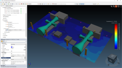
...but if we look at a risk isosurface setting looking at Exceedance of 10% LFL and Scenario count of 80 or more we see that most of the gas accumulates at the upper elevation of the building. This can also be confirmed by moving the contour to a higher offset distance.
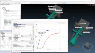
With this information gas detector optimization can be performed. You may use monitor points to define plausible detector locations or have in:Flux suggest the mathematically optimal locations based on the simulations run by selecting the Optimization Algorithm to Optimal Layout. The below has 8 point gas detectors defined at the HVAC outlets (2 per outlet). The optimization shows that 74% of the scenarios run were able to be detected by just 3 point gas detectors with a low alarm setting of 20%LEL.
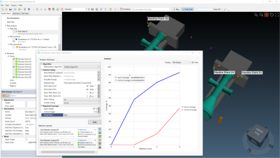
If we continue by applying a consequence value to each of the cases using the Risk Manager, a risk-based optimization can be done. The below scaled the consequence values by the size of the resulting gas cloud generated by each case. The optimization can be run again changing the Target Basis to Risk (rather than scenario used above).
This shows us that for the simulations run, using 3 point gas detectors near the HVAC outlets provides a 92.8% risk reduction.
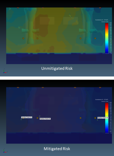
A new risk data set can be created to produce an unmitigated vs mitigated risk figure - process for creating the below is described here. The below shows a contour at 11m height of exceedance of 10%LFL for the cases simulated before gas detection and after.