Adding an Inflow
Five types of inflows can be added to an in:Flux project, some for dispersion, some for fire only and some for internal ventilation only:
-
High Pressure Gas Leak - upstream pressure, upstream temperature, hole size, and discharge coefficient are needed as inputs
-
Custom Gas Emission - velocity, temperature, hole size and shape are inputs
-
Evaporating Pool - for fire simulations only, used when calculating liquid pool evaporation
-
HVAC - used with internal ventilation simulations and has four types:
-
Forced Inlet - a fan that forces air into the system at a specified flow rate
-
Forced Outlet - a fan that forces air out of the system at a specified flow rate
-
Through-Flow Fan - a fan which flow can pass through it at a specified rate
-
Passive Opening - open region that allows flow in or out of simulation, not forced, a zero pressure boundary
-
-
Group - a collection of multiple leaks combined together to be calculated together as a single inflow.
In in:Flux, releases can be pointed in any direction: pointing into the wind, away from the wind, off axis, and even directly pointed towards equipment or the ground. For this tutorial we will be adding a high pressure leak pointing at a perpendicular to the wind simulation that was calculated in Tutorial 1.
-
Click the Add Item tab and select Gas Leak or Emission from the dropdown menu.
-
Set the Type as High Pressure Gas Leak
-
Leave the name as "HP Release 01". in:Flux will automatically recognize and increment the naming convention you use, e.g. HP Release 01 will increment to HP Release 02 once the first has been added to the project. More about the automatic naming is described in the Advanced Capabilities section.
-
Set the Gas to METHANE from the dropdown menu. Here you can select varying pure gases from the DIPPR® database, or click the database icon
 . Gas mixtures can also be created and is discussed later in Tutorial 7.
 -
Leave the Upstream Pressure set to "10" bar(g). Note that you can click the bar(g) text to select other units, e.g. atm, bar(a), Pa, and psi as shown in the figure below.
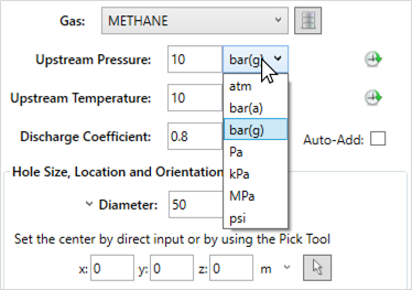
Tutorial 2 - Figure 02 - Selection of varying units for the upstream pressure in a HP leak definition
-
For the methane gas, enter a value of "10" C for the Upstream Temperature
-
Leave the Discharge Coefficient as "0.8".
-
Enter a value of "50" mm as the Diameter. Here you may also enter the flow rate (in kg/s or kg/hr) of the leak rather than the diameter of the hole size, either may be used.
-
For the Location, click the pick tool button
 next to the x, y, and z coordinate text boxes as indicated below. This will activate the Point Pick Tool for choosing a location for the leak and freeze the movement of the 3D window. A yellow crosshair icon will follow your mouse pointer with displayed coordinates of the current position. Press Ctrl to pause or suspend the pick tool (this is a toggled option) so that you may move the 3D window without selecting a point. Position your screen to be similar to Figure 03 below.
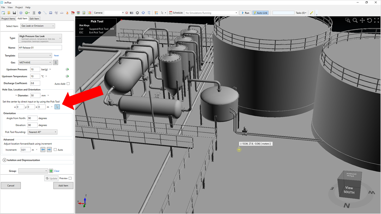
Tutorial 2 - Figure 03 - Suspended Pick Tool in the 3D window to allow for pan, rotate, and zoom without selecting a point.
-
Zoom into the flange coming out of the top of the tank in the middle of Figure 03, press Ctrl again to toggle off the suspension of the pick tool and select a point on the flange on its northern edge as shown in Figure 04 and Figure 05 below.
-
Alternatively, you may enter "-6.6, 22.95, 5.94" as the x, y, and z coordinates of the leak location. The entered coordinate may be slightly different from the values obtained from the pick tool, this tutorial will use the values shown in Figure 04 below.
-
-
If the pick tool is used for choosing a coordinate of the leak, the normal vector of the chosen point is automatically entered as the Angle from North value with an accuracy equivalent to the Pick Tool Rounding. If the coordinate is entered manually, then you will need to manually enter the orientation for the leak. Regardless of your method of entry, ensure that the Angle from North set as "0" and Elevation as "0" before continuing.
-
if any warning appears stating the inflow is blocked by nearby geometry, click once on the forward button
 in the Advanced section
to slightly move the leak to be infront of the surface. This should not occur if the pick tool is used for this example.
in the Advanced section
to slightly move the leak to be infront of the surface. This should not occur if the pick tool is used for this example.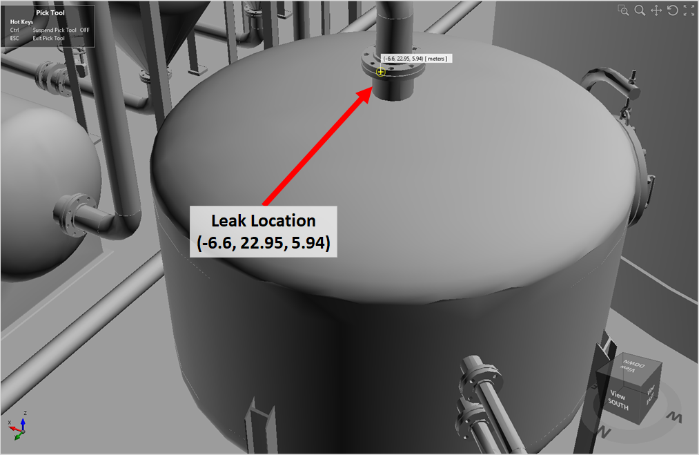
Tutorial 2 - Figure 04 - Zoomed into location for the high pressure leak.
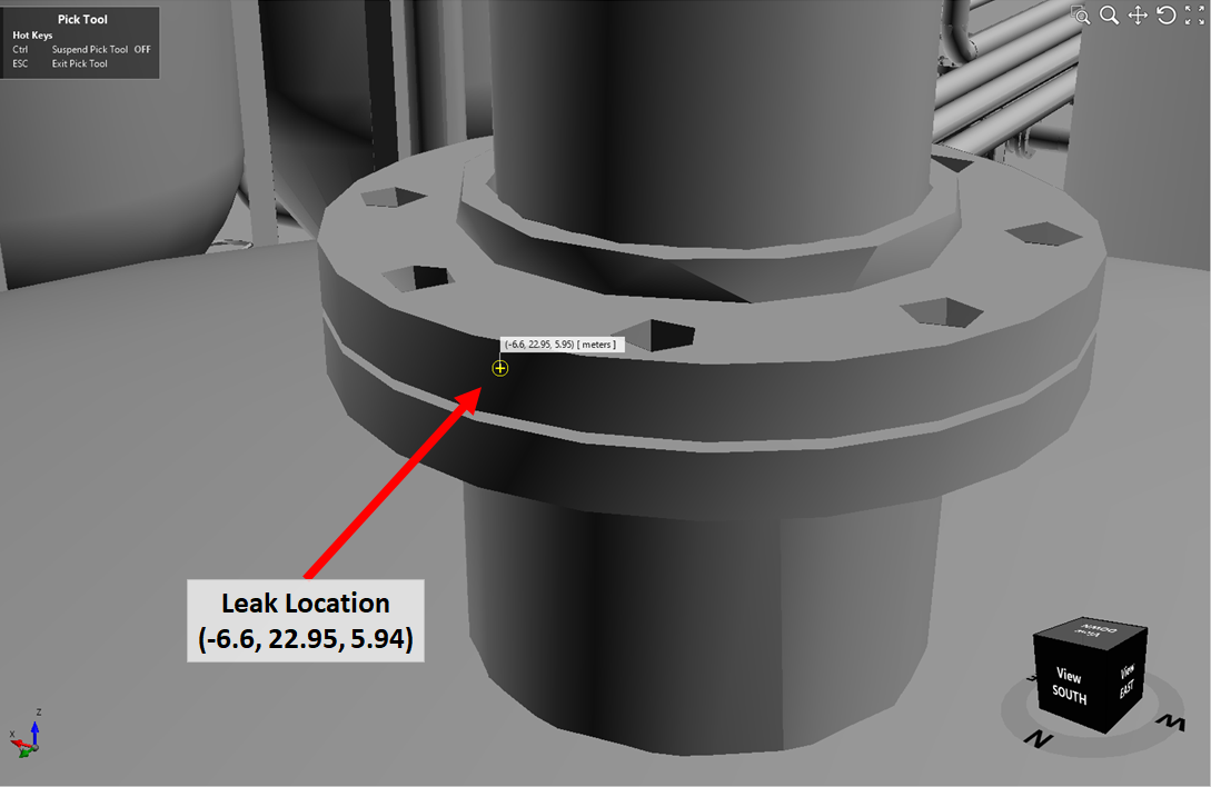
Tutorial 2 - Figure 05 - Closer view of leak location with labeled coordinate
-
-
Click the Preview checkbox at the bottom left of the screen. A red truncated cone with an arrow should be visible, as in the picture below.
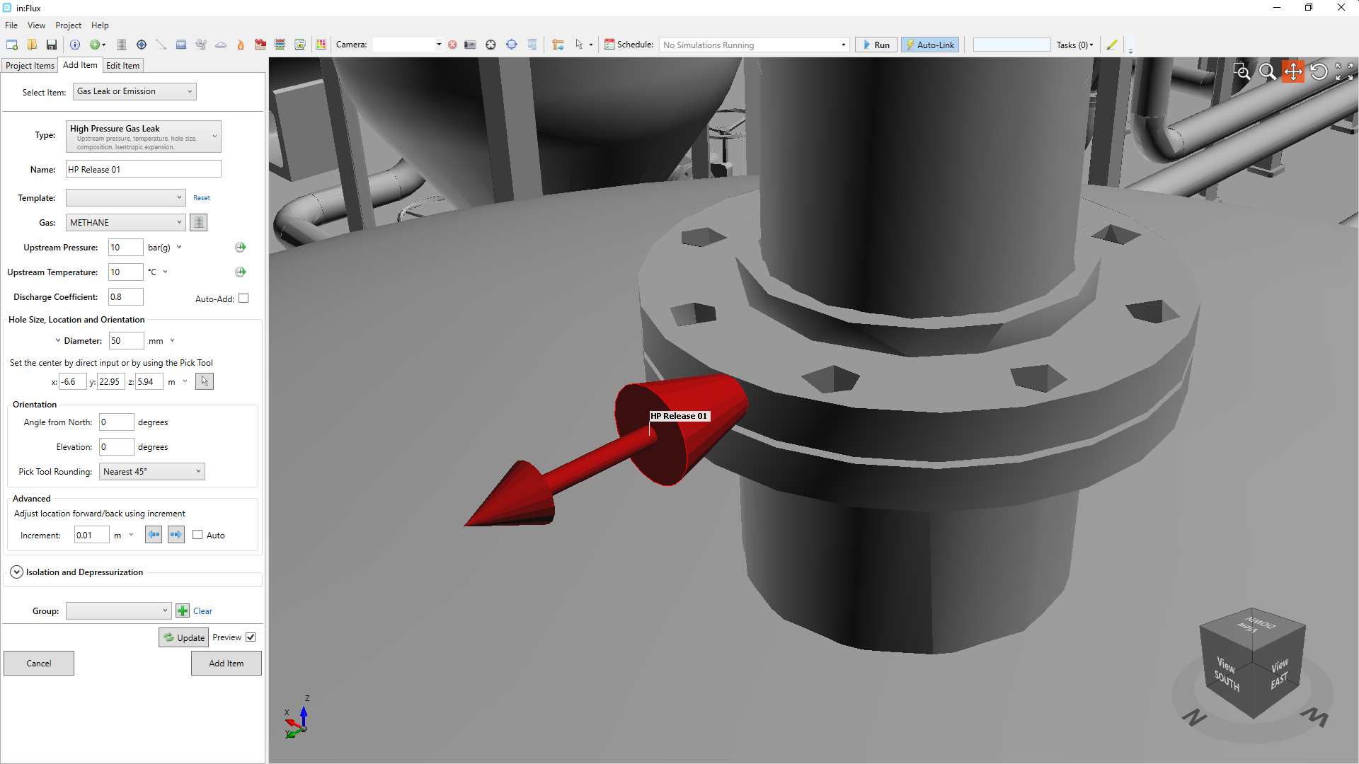
Tutorial 2 - Figure 06 - Preview of the high pressure leak.
-
Leave the other settings alone for now and click the Add Item button.
The leak icon should now appear green in color, as in Figure 07 below, and will have been added to the Project Items tab under the Inflows -> Gas Leaks, Exhausts and Liquid Pools header.
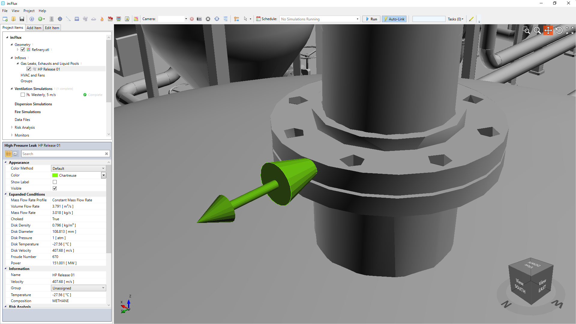
Tutorial 2 - Figure 07 - Addition of HP Release 01 to the Project Items tab, changing from a red item (previewed) to a green item (added to the project).
Proceed to the next section for setting up and running a dispersion simulation.