Geographic Fire and Gas Mapping Guide
The below is a short summary of suggested steps for performing fire and gas mapping (FGM) analysis using the geographic method. There are several approaches to this method which will differ from company to company, Detect3D has been designed to work with any performance standard (e.g. BP GP 30-83, Shell DEP 32.30.20.11, or ISA TR 84.00.07). It is always up to the user to determine the best approach needed for their project. Refer to the Detect3D Documentation for more specific information on how to carry out each step described below.
F&G Mapping Analysis Steps:
-
Identify the hazardous event(s) to be detected and set performance targets. This would be the size and type of fire, the gas cloud size (both for toxic and combustible gases) and coverage target needed. Typically this is stated in the project's performance standard.
-
Identify regions or equipment with risk of event occurring. It is important to determine which regions need detection and which regions do not. Defining a large region or zone covering the entire facility will lead to higher detector counts as coverage will be provided where there is little or no risk.
-
Import or create 3D CAD geometry model
-
Define fire and/or gas zones in regions identified in Step 2. Sub-zone regions can be defined to highlight high risk areas or individual pieces of equipment
-
Define flame detector model field-of-view (FOV) based on chosen manufacturer spec sheets and identified performance target identified in Step 1 (fire size and fuel type)
-
Position flame detector devices around the facility in existing locations or proposed locations
-
Define and position gas detectors (combustible and/or toxic) based on gas cloud size or from existing locations. Depending on the performance standard, the congestion in each zone should be calculated for this step to determine appropriate gas cloud size to use in the analysis. Apply the determined gas cloud size to the zone's risk grade.
-
Review obtained coverage for each zone and/or sub-zone region
-
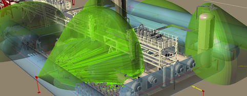
Define contours and isovolumes to assist in determining where blind spots exist as well as redundant coverage regions.
-
Assess if modifications are needed for the layout based on achieved coverage in Step 8. If coverage is not adequate, then re-position and/or add devices as needed. Detect3D’s Detector Rankings Tool and Detector Contributions Tool can be used to determine the most and least effective devices in the analysis for a chosen zone or sub-zone. Additionally, Detect3D's Optimization Tool may be utilized for flame detector positioning. Steps 6 through 8 may be iterated several times until the desired coverage or performance metric is achieved.
-
Output results of achieved coverage and detector locations to Excel or PDF. Detectors may also be exported to a DWG CAD file.
-
Provide supporting images and screenshots to adequately convey detector layouts achieving performance targets.